
Switching Challenges in Power Modules

In an application such as motor drives, a speed of 15 kilohertz is more than adequate. Beyond that, devices operating at up to 40 kilohertz are possible, particularly in higher power applications.
A full silicon carbide solution may not even be required in this case, because we know that there are good silicon devices, particularly at 650 volts, that provide good trade-offs so that you can actually select the right chips and also add silicon to get a very good benefit and efficiency results.
Multi-level topologies lend themselves well to a hybrid silicon carbide solution, so you can keep the switch as an IGBT power module and simply swap out the freewheeling diode for a silicon carbide device. This type of solution can already save you up to 50% on your energy bills.
Higher switching frequencies of 40 kilohertz and above are where full silicon carbide should be discussed. Efficiency, modulation accuracy, and, hopefully, a reduction in size and cost at the end.
Challenges
Let’s take a look at systems with current ratings of 20 amps or higher, as well as commutation inductance. Lower inductance translates to faster switching, higher voltages, and higher currents. Thermal performance is critical, so we must incorporate new technologies in the power module to ensure that the silicon carbide chip is used to its full potential.
When we look at a system design like the one in Figure 1, we see a half-pitch module with obvious parasitic stray inductances, and when we turn off a switch, we see a DC bus voltage, but when we measure the voltage on the IGBT module, we see an even higher voltage.
Why is this the case? We’ve seen voltage drop over the stray inductances simply because of the di/dt and the change in current. This happens in every switching incident, so it must be seriously considered.
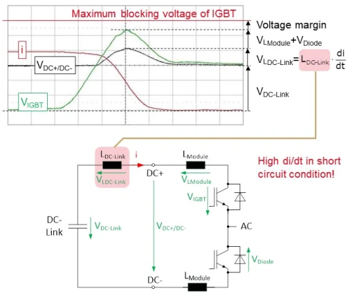
Fig. 1: Stray inductances are present in every switching event.
Another point to consider is oscillations, also known as hysteresis. When you switch faster, you will experience oscillations caused by parasitic inductances and capacitances. It is critical, of course, that you do not exceed the device’s maximum clocking voltage with this over-voltage.
If stray inductances cannot be reduced, switching must be made slower. As a result, you end up losing performance. Of course, you can also lose maximum DC bus voltage, so we must run the entire system at a lower DC bus voltage just to ensure that there is enough margin to this breakdown voltage.
Reducing Inductance
When you look at how the parasitic components are split up in this power module, you’ll notice that there are a lot of stray inductances coming from the bond wires and DBC traces in the connections to the outside to the load or to the DC bus.
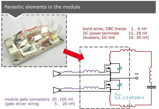
Fig. 2: Notice how the parasitic components in this power module are actually split up.
How do we go about optimizing something? The area that your commutation loop spans directly affects clear inductance. So, obviously, you must keep the DC+, DC- loop, which is always in the conduction loop, as small as possible.
It ends up at 25 nanohenry in Figure 3, where DC+ and DC- are quite far apart. If you can lead these terminals, which are actually modular terminals, in parallel, this inductance decreases. It’s a very simple procedure. It’s not as simple in some other modules. Thus, a 11 nanohenry is already a good deal.
The gate inductance is also an important consideration. And it was discovered that a low gate inductance is not really desirable. We tested a lot of different modules with a lot of different gate inductances and discovered that if you plot the switching losses over the gate inductance, you can see that there is an optimum that is not at 0.
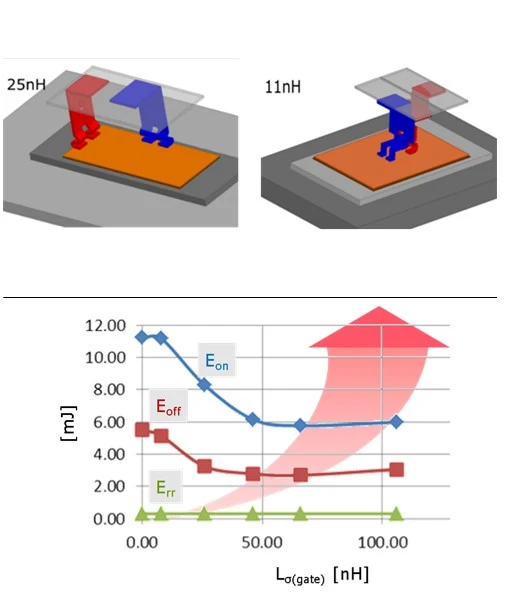
Fig. 3: Inductance decreases when the modular terminals are led in parallel.
The reason for this is that a small gate inductance will act as a current boost in the Miller plateau during the switching process. This is very beneficial. We find an optimum in the 15 to 17 nanohenry range.
Lower than this requires a much more powerful driver to really push the current inside. If you go higher, the inductance will simply slow the switching process down.
Thermal Management
The current density in silicon carbide is much higher, owing to the fact that there are fewer switching losses and gains in forward losses, as well as the fact that the chips are very small.
Finally, you lose thermal performance because the Rth of your chip, for example, the thermal resistance of the entire IGBT power module, is dependent on the chip area you place inside.
A simple way to accomplish this is to change the ceramic substrate that we use to place the chip on, as well as to provide isolation for the heat sink. For example, aluminum oxide, which is currently the standard, has a specific thermal connectivity, a specific thickness, and thus a specific thermal performance.
We now have a choice between two different materials. Silicon nitride is a very stable and robust material that provides a much better thermal performance or thermal connectivity of 90 watts per meter Kelvin.
Aluminum nitride could also be used as an alternative.
Even better thermal performance, but because it is brittle, it’s better to use it at a higher thickness, which, of course, gives up some of the thermal improvement, but in the end, this higher thermal connectivity compensates, so these two materials are basically equal.
If we change the ceramic material to aluminum nitride, we can actually reduce the number of chips and thus the cost of the power module. The Rth per chip is still better, the drain current that can be run continuously is nearly the same, but the overall cost of the module is lower. This is a nice, simple way to optimize the IGBT module while also minimizing the number of chips used and lowering the overall cost of the power module.
Another factor to consider is the coefficient of thermal expansion. With each thermal or power cycling, all the materials expand, and unfortunately, all materials in a materials stack up in a power module have a different coefficient.
You can actually bring these coefficients closer together if you use the right materials. Aluminum oxide silicon is the current standard. As you can see, the difference between these two coefficients is quite large. However, if only the standard module is changed to silicon carbide, the gap widens.